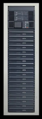
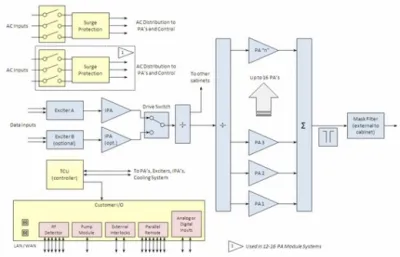
· PowerSmart technology, for best-in-class power efficiency and lowest operating costs
· Rugged, reliable design and construction
· Digital power levels up to 33.6 kW ATSC, 28.8 kW DAB and 19.2 kW
DVB-T/DVB-T2/ISDB-Tb
· Analog power levels up to 48 kW
· Incorporates field-proven Maxiva M2X exciter technology, allowing easy migration from analog to digital or between different standards
· All-digital linear and nonlinear pre-correction, including exclusive Real-Time Adaptive Correction (RTAC™)
· Fully broadband PA ruggedized modules — 168 to 242 MHz
· 1:1 PA pallet to power supply redundancy
· Hot-pluggable linear RF amplifier modules
· Transmitter monitoring and in-depth diagnostics via easy-to-use, front-panel controls
· Web-enabled remote control graphical user interface
Specifications and designs are subject to change without notice.
|
General |
|
|
Frequency Range |
168 to 242 MHz, in 1 Hz steps |
|
Transmission Standards |
ATSC, DVB-T, DVB-T2, ISDB-Tb, Analog, DAB |
|
Channel Bandwidth |
1.5, 6, 7 or 8 MHz (system dependent) |
|
Rated Power Output |
See chart below |
|
Output Power Reduction Range |
0 to -10 dB |
|
RF Load Impedance |
50 ohms |
|
VSWR |
Protected against open or short circuit, all phase angles. Capable of operation into infinite VSWR with user-adjustable fold back threshold. Factory pre-set to 4% of nominal nameplate power (VSWR = 1.5:1) |
|
RF Output Connector |
N-female, 1-5/8 or 3-1/8 in. EIA (dependent upon power level, DIN 7-16 optional for lower power levels) |
|
Transmitter Dimensions |
Refer to outline drawing 8398464263 |
|
Transmitter Weight |
Refer to outline drawing 8398464263 |
|
AC Mains |
|
|
AC Line Voltage |
3 phase: 380 to 415 V, or 208 to 240 V, 50/60 Hz - specify when ordering |
|
AC Line Variation |
±15%, between 208 to 230 V, or 380 to 400 V |
|
Power Factor |
>0.97 (0.98 typical) |
|
Environmental |
|
|
Altitude |
Up to 13,123 ft (4,000 m) elevation above mean sea level |
|
Ambient Temperature |
32° to 113° F (0° to 45° C) at sea level (upper limit derated 3.6° F (2° C) per 984 ft (300 m) elevation AMSL) |
|
Humidity |
95%, non-condensing |
|
Cooling Method |
Liquid-cooled, using 50/50 mix of ethylene or propylene glycol and water |
|
Acoustic Noise |
<65 dBA (measured 1 m (3.3 ft) in front of cabinet) |
|
Frequency Stability |
Without precision frequency control/GPS: ±150 Hz/month (6.2 x 10⁻⁷ppm) |
|
External Inputs |
|
|
GPS Input |
SMA female, 50 ohms, (+5 V DC @ 100 mA max output for active antenna) |
|
1 PPS Input |
BNC female, user selectable 50 ohms or high impedance termination |
|
10 MHz Reference Frequency |
|
|
Input |
BNC female, 50 ohms |
|
Monitoring Outputs |
|
|
RF Monitor (exciter) |
SMA female |
|
1 PPS |
BNC female |
|
10 MHz |
BNC female |
|
DVB-T/DVB-T2 / ISDB-Tb Specification |
|
|
Power Output (average) |
800 W to 6.4 kW models available, measured before mask filter (see chart below) |
|
Systems |
DVB-T, standard EN 300744 |
|
ASI/T2MI Inputs |
2 inputs BNC female; 75 ohms according to EN 50083-9 (2 main/2 hierarchical) |
|
Crest Factor |
13 dB maximum |
|
Shoulder Level |
<-37 dB (before mask filter) |
|
END |
<0.5 dB |
|
MER |
>33 dB (typical 35 dB) |
|
Harmonics (before filter) |
<-40 dB |
|
Central Carrier Suppression |
>75 dB |
|
DVB-T2 Modes |
Supports multiple PLP’s, MISO, extended bandwidth mode, PAPR reduction |
|
DAB/DMB Specification |
|
|
Power Output (average) |
1.2 kW to 9.6 kW models available, measured before mask filter (see chart below) |
|
Systems |
DAB/DMB (OFDM) ETSI EN 300 401 & ETSI TR101 496-1 |
|
Power Stability |
≤ ±0.25 dB |
|
Harmonic/Spurious Output |
Complies with EN 302077-2 when used in conjunction with proper band pass filter |
|
Shoulder Before Filter |
35 dB minimum, >36 to 40 dB typical |
|
MER |
>25 dB |
|
Signal Inputs |
ETI Input: BNC-female, user selectable 75 ohms or high impedance termination. 2x ETI (NI, G703) or 2x ETI (NA, G704), seamless input signal switch-over automatic optional |
|
Monitoring Outputs |
ETI Monitor |
|
ATSC Specification |
|
|
Power Output (average) |
1.4 kW to 11.2 kW models available, measured before mask filter (see chart below) |
|
System |
ATSC A-53, 8-VSB DTV standard |
|
Data Input |
19.39 Mb/s, configurable as SMPTE-310M or ASI (user selectable) |
|
Impedance |
75 ohms, unbalanced |
|
Input Connector |
2 inputs, BNC female |
|
Signal to Noise (EVM) |
>27 dB (EVM < 4%), Typical >32 dB (EVM <2.5 %) |
|
Phase Noise |
<104 dBc/Hz @ 20 kHz offset (ATSC A/64) |
|
Harmonic Radiation and Spurious |
Meets mask requirements specified in FCC 5th and 6th report and order |
|
Sideband Performance |
Compliant with FCC radiation mask, when measured at the output of GatesAir-supplied output filter |
|
Analog |
|
|
Power Output |
|
|
(vision peak of sync) |
2.0 kW to 16 kW models available, measured before IMD filter (see chart below). 10% Sound |
|
Analog Television Systems |
CCIR G, I, K, K1, M, N |
|
Color Systems |
PAL, NTSC, SECAM |
|
Sound Systems |
Monaural, BTSC, IRT, NICAM G |
|
Analog Video Performance |
|
|
Video Input |
0.7 to 1.4 V, 75 ohms, 32 dB return loss |
|
Variation of Output Power2 |
±2% |
|
Vision Sideband Response3 |
PAL system G shown (other systems available) |
|
Differential Gain5 |
3% |
|
Differential Phase5 |
3° |
|
Low Frequency Linearity6 |
10% |
|
Incidental Carrier Phase Modulation5 |
±2° |
|
Signal to Noise Ratio |
>60 dB (weighted) |
|
K Factor |
2% or less with 2T sin2 pulse |
|
20T Equivalent Gain and Delay |
3% total baseline distortion |
|
Spurious and Harmonic Radiation |
-60 dB, or better |
|
In-Channel Intermodulation Distortion |
-58 dB (-60 dB typical) |
|
Analog Sound Performance |
|
|
Modulation Capability |
±120 kHz peak deviation |
|
Monaural Input |
Adjustable 0 to 12 dBm, 600 ohms, balanced, >30 dB return loss |
|
Pre-emphasis |
Selectable 75 or 50 µS |
|
Frequency Response |
±0.5 dB, 40 Hz to 15 kHz |
|
Harmonic Distortion |
0.5%, 30 Hz to 15 kHz |
|
FM Noise |
60 dB RMS with de-emphasis |
|
AM Noise |
50 dB RMS from 30 Hz to 15 kHz |
|
Synchronous AM Noise |
40 dB RMS at 400 Hz with ±25 kHz deviation |
|
IRT Sound |
Available |
|
NICAM Sound |
Available |
|
Remote Control |
|
|
Parallel Remote |
12 conductor terminal block (mini Wago) |
|
Ethernet/SNMP |
RJ-45, twisted pair |
|
Compliance |
RoHS 2002/95/EC |
|
1 Variation of peak output power with a change in average picture level from black to white (0% to 100%). |
|
|
2 Peak-to-peak variation of peak sync voltage during one field using field test signal per EIA-508. |
|
|
3 Response specified for transmitter operating into a resistive load of 1.05:1 VSWR. |
|
|
4 Measured using 20% peak-to-peak amplitude swept video modulation with pedestal set at 10%, 50% and 90% APL. All percentages relative to a blanking to white transition. |
|
|
5 Measured using a 5-step staircase signal. Test signal #3, CCIR REC. #421-3. |
|
|
VLX Power Levels |
||||||||||||||||||||||||||||||||||||||||||||||||||||||||||||||||||||||||||||||||||||
Modulationsb · AN – Analog · AT – ATSC · DV – DVB-T · T2 – DVB-T2 · IS – ISDB-Tb |


